7
"Everything that can be invented has been invented."
Charles H. Duell, Commissioner, U.S. Office of Patents, 1899
Chapter 1 - Hardware
This chapter presents the hardware components I have developed to operate interactive AR applications such as Tinmith-Metro in an outdoor environment. AR requires that equipment such as a HMD, computer, and tracking hardware be worn outdoors, with some early examples being the Touring Machine by Feiner et al. [FEIN97] and my initial research prototypes [THOM98] [PIEK99c]. While my research was initially based on similar applications as Feiner et al., over time I have moved into the new areas of research that are described in this dissertation. This research requires new hardware components capable of supporting the desired interactions. While commercially available components are used in many cases, these must be modified to suit the requirements of the mobile AR task. In some cases, components cannot be purchased off the shelf and so must be designed and constructed. This chapter describes the integration of existing components and the development of a custom backpack, helmet, and gloves to support the research in this dissertation.
1.1 Hardware inventory
This section describes the equipment that I currently use to perform AR outdoors. Previous generations of backpacks and associated components are discussed in the appendix of this dissertation. Table 7‑1 summarises the equipment options currently in use, including cost, placement on the body, and power consumption.
Current generation
laptops are almost on par with the processing capabilities available in desktop
machines. While there is still a slight delay with new technology in laptops,
there is now a demand from consumers for laptops that can run the same
applications as desktops. The current laptop used is a Dell Inspiron 8100 with
Pentium-III 1.2 GHz processor, 512 mb of memory, and a 20 Gb hard drive. Most
importantly of all, it contains an Nvidia GeForce2Go graphics chipset that is
capable of rendering complex 3D texture mapped graphics with hardware
accelerated OpenGL support. Using two Lithium-Ion batteries it can store
approximately 110 Wh of power and operate for more than 2 hours. The laptop
runs a custom compiled Linux kernel 2.4 with the RedHat Linux 7.3 distribution,
which includes various libraries and tools from GNU, BSD, and the X Consortium.
|
|
|
Location: H=head, B=backpack, W=worn Table 2‑1 Current backpack components with cost, location, and power consumption |
The head mounted display is a Sony Glasstron PLM-700E with a maximum resolution of 800x600. As discussed previously, this display can be used for either video or optical-based augmented reality, and has one of the highest quality displays available. Since this display is no longer available, a set of IO-Glasses with PAL video resolution is used for performing demonstrations to the public.
The body position tracker used is a Trimble Ag132 GPS. As discussed previously, this device uses differential signals, advanced signal processing, and higher resolution calculations to produce 50 cm accuracy. The device outputs NMEA 0183 updates via an RS-232 serial port at 10 Hz, making it very suitable for position sensing in AR. The secondary GPS unit also supported is a Garmin 12XL GPS, which is much lower quality with 5-10 metre accuracy at 1 Hz with NMEA 0183 updates.
The head orientation tracker is an InterSense IS-300 hybrid magnetic and inertial tracker, with the sensor cube mounted on the helmet. This device produces updates via an RS-232 serial port at up to 300 Hz, but configured at the rate of 30 Hz so that the laptop processor is not saturated by the tracker data.
The video input is captured by a Point Grey Research Firefly camera, which uses a 1394 Firewire interface [IEEE95] to directly connect to the laptop. This camera is a Digital Camera (DC) compliant 1394 device that can output 640x480 resolution video at 15 frames per second in an uncompressed 24-bit RGB format. Using uncompressed RGB is more efficient than YUV formats because it can be passed directly to OpenGL and image processing algorithms with no conversions in the processor. The Firefly camera is separated into two parts via a ribbon cable - the small CCD sensor and lens are mounted onto the HMD while the processing is performed on a separate board in the helmet. An alternate camera used with the IO-Glasses for demonstrations is a Pyro 1394 web cam, supporting the same video formats as the Firefly but with a lower resolution camera sensor internally.
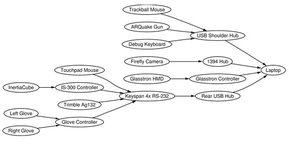
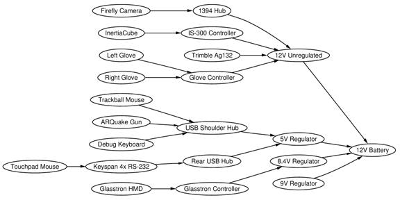
Other
supporting components such as USB hubs, 1394 Firewire hubs, and USB to RS-232
converters are also required to connect hardware that may not share a similar
interface or provide enough connector plugs. Figure 7‑1 depicts the flow
of data from each component as it is propagated toward the laptop for
processing.
|
|
1.2 Tinmith-Endeavour backpack
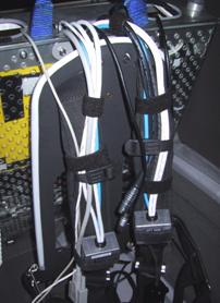
I have
been developing backpack computers for the last five years to support AR
software. The original design shown in Figure 7‑2 was used for a number
of years to support my research, and was based on a hiking frame that was
untidy and difficult to maintain. As part of a joint research venture between
UniSA and DSTO, I worked with a team of engineers from the SES and ITD
divisions at DSTO to gather requirements and analyse my previous backpack
designs. The goal was to produce a new backpack using industrial manufacturing
techniques to support mobile AR. The final product is of professional build
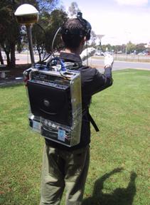
quality and is shown in Figure 7‑3. This section presents how
Tinmith-Endeavour evolved from the previous designs, with the lessons learned
along the way and how these were used to help improve the design. The appendix
contains a complete discussion of the various backpack designs I have created
since the start of this dissertation.
|
|
|
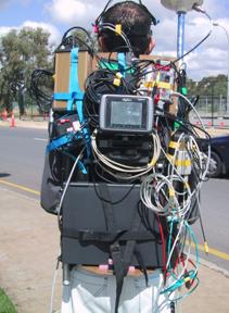
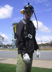
Figure 2‑2 Rear view of previous backpack design, showing tangled mess of cabling
Figure 2‑3 Front and rear views of the Tinmith-Endeavour backpack in use outdoors |
The technology of the components for AR research has been rapidly changing over the past few years and it is not possible to keep a static design due to constant hardware upgrades. For example, in the last two years video capture in laptops has changed from analogue PCMCIA to USB, and now to 1394 Firewire. Most input devices are now USB, although some legacy devices must still be supported with PS/2 and RS-232 ports. Merely placing all the items into a rucksack style container is not possible due to the number of cables and various sizes and weights of the devices. From my analysis, a rigid frame that the devices can attach to is the best solution, as it allows enough flexibility to accommodate future changes, even for unknown devices.
1.2.1 Previous designs
The original backpack shown in Figure 7‑2 is based on a hiking frame, containing aluminium pipes running along the sides and across. Wooden back planes and straps are used to attach components but the number of pipes to attach to is limited. Wires are routed using insulation tape to hold them together and to the backpack, and requires cutting to remove and leaves a sticky residue. The laptop is supported by a perpendicular wooden plane at the bottom and then strapped to the backpack both horizontally and vertically, and prevents access to the laptop without removing the straps. While this design works, it is time consuming when problems occur or equipment needs changing. A number of problems were identified from the previous backpack designs during the requirements gathering process. Some of the problems identified were:
· Hardware changes - Hardware is continuously improving and reconfiguring components was difficult because many could only fit in certain places on the hiking frame due to its shape.
Breakage - Fragile connectors and cables were breaking easily because they were not protected from external forces experienced when moving in the environment.
Travel - The backpack was difficult to transport to overseas demonstrations due to its size and fragility.
Fasteners - Insulation tape was used to fasten cables and components, which leaves a sticky residue.
Cable bundling - Bundles of cables taped together are messy and waste space otherwise available for other components.
Laptop fastening - Straps holding the laptop in place prevented it from being opened, making setup and debugging difficult.
Autonomous operation - The cabling was so complicated it required an assistant to help prepare the user for outdoor use.
Power supply - Many devices contained their own power sources with different lengths of operation, a centralised battery would simplify the operation of the backpack.
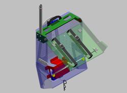
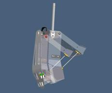
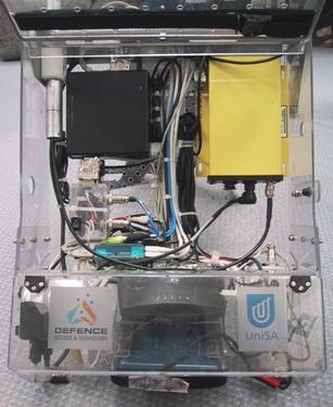
1.2.2 Frame design
The new
backpack design is worn by using an industrial breathing apparatus frame. The
frame is made of aluminium with a foam padded interior and moulds to the contours
of the body. The rest of the system is contained within a clear polycarbonate
moulded box with a pattern of holes drilled over the surface, providing
mounting points and air flow. The polycarbonate box and frame are joined
together with a hinge, allowing the entire backpack to open into an A shape and
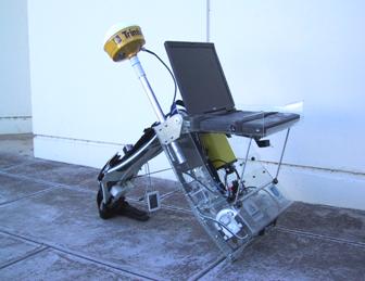
be self supporting outdoors if required. The polycarbonate box depicted in
Figure 7‑4 is used to mount all the components in, and a second box is
mounted inside on a hinge to hold the laptop - when the backpack is in the A
shape, it is possible to fold the laptop out like a table, as shown in Figure 7‑5.
This design allows the backpack to be placed on the ground outdoors to operate
the laptop in a traditional manner.
|
|
1.2.3 Attachments
Attaching
devices to the backpack is difficult since many devices are manufactured with
no mounting points and little surface area to attach to or drill into. As a
result, a variety of strategies are needed to fix devices securely to the
backpack. With the previous designs, straps, double-sided tape, and permanent
screw mountings were used. The new interior design of the backpack is shown in
Figure 7‑6, with components fixed securely using Velcro and cables
attached with cable ties.
|
|
A special 3M developed Velcro is used as the main means of attaching large components. This Velcro uses mushroom-shaped plastic heads and four 1cm x 1 cm pieces can securely suspend the laptop vertically. For safety, two straps run across the laptop keyboard are used to protect it from falling if the Velcro were to fail. Components inside the backpack also use Velcro but do not require safety straps because they are lightweight and attached cables would provide support if the device detaches during use. Using the Velcro enables easy rearranging of components as hardware requirements change and small surface areas can support quite heavy objects.
Cables are run along the surface of the polycarbonate in busses, with cable ties through the plastic grid holes to secure them. This still does not truly solve the problem of easy configuration since they must be destructively cut open when new cables are added or removed. Since they are cheap, they are used in preference to insulator tape which does not run well through holes and leaves a sticky residue. It would be desirable to use some kind of reusable cable ties that can hold large bundles of wires easily.
1.2.4 Power supply
Many of the components used require their own battery, and so using a single dense power source means that all devices run for the same amount of time. In the past, heavy lead acid 12V batteries were used but these have been replaced with 12V Nickel Metal Hydride (NiMH) batteries rated at 100 Wh. This battery powers all of the components except the laptop for approximately 1.5 hours (varying depending on the equipment in use) and may be swapped by an assistant while mobile. Linear voltage regulators are used to run low current devices at 5 and 9 volts, as well as the Sony Glasstron which uses a non-standard 8.4V. The Glasstron uses 1.2A of current at 60% efficiency due to the linear regulators, but the additional cost and weight of a DC-DC converter was not deemed necessary and instead spent on extra NiMH batteries.
To
distribute power, a specially designed breakout box shown in Figure 7‑7
is used that has 8 four pin connectors, each with GND, +5V, +9V, and +12V available.
Devices may be easily plugged in since one standard type of connector is used
throughout the system (except for the Sony Glasstron). Power breakout boxes may
be chained if more sockets are needed. A master power switch (with 5 Amp fuse
and indicator light) is mounted onto the front shoulder strap to allow the user
to easily turn the power on and off without having to remove the backpack.
|
|
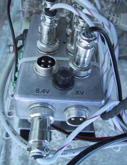
Figure 7‑8
depicts how the various devices in the system acquire their power. Some devices
are connected directly to the breakout box while others receive it over their
data bus connections.
|
|
1.2.5 Connectors and
cabling
|
|
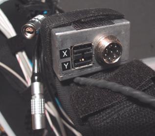
To make the system easy to use while outdoors, a number of connectors are available on the shoulder straps to attach devices to, as shown in Figure 7‑9. Four USB sockets are available on the shoulder straps, allowing the user to plug in devices such as mice and keyboards for debugging while mobile. Special Lemo connectors are used to attach the 1394 video cable and IS-300 sensing cube, permitting the separation of the HMD from the backpack. 8-pin sockets that attach to leads ending in Mini-DIN connectors are used for the glove interface and are easy to plug in, even while wearing the gloves. Since the 50-pin Sony Glasstron cable cannot be cut for a connector, the entire unit is attached with Velcro so it can be separated.
Internally, cables have been shortened where possible to approximate lengths or tied into tight looms and cable tied to the plastic grid on the backpack. The backplane allows many separate bundles and so different subsystems are separated to allow changes without affecting the rest of the cables. One risk of using tight cable ties is that they could potentially damage fragile cables (such as the Glasstron 50-pin cable) if used incorrectly.
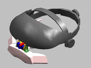
1.2.6 Helmet
The Sony
Glasstron HMD is a very fragile device and has a limited surface area for
attaching extra components such as trackers and cameras. Rather than attempting
to weigh down the small hinge on the front of the HMD, the head band of the
Glasstron is attached to a welding helmet that has a semi-rigid plastic frame
permitting attachments. The IS-300 sensor cube is mounted on the top of the
helmet shield with plastic mushroom Velcro, while the Firefly camera processing
board is hidden underneath the shield. The small CCD sensor for the Firefly
camera is mounted onto the HMD using a custom manufactured bracket with screws
to adjust the angle, and a flexible ribbon cable connecting it to the
processing board. The helmet design is depicted in Figure 7‑10, and
photos were shown previously in Figure 1‑1 and Figure 7‑3. As
mentioned previously, for demonstration purposes an IO-Glasses HMD with Pyro
1394 camera is used and includes sufficient mounting space so that an extra
welding helmet is not required.
|
|
|
Figure 2‑10 Design of brackets to attach Sony Glasstron and Firefly camera to a helmet (Image courtesy of ITD and SES – Defence Science Technology Organisation) |
1.2.7 Transportation
Since this research is being conducted in Australia, presentations at conferences usually require travel on airplanes. Airlines are known to handle baggage very roughly and transporting delicate computer equipment can be difficult. A special aluminium suitcase was designed to transport the backpack, containing foam blocks that have been carved out to fit the profile of the backpack. This foam is soft and protects the equipment from shocks while being transported, reducing possible damage to the backpack and improving reliability for demonstrations.
While the foam suitcase adequately protects the backpack, the vibrations and other shocks experienced during transport still manage to separate connectors and Velcro, requiring small touch up repairs on arrival. Devices such as the laptop, GPS, IS-300, and HMD are too fragile to be transported in this way and so are packed into a separate carry bag as hand luggage. This bag has much thinner padding and is designed to fit into the overhead compartment of an aircraft, with the assumption that the person carrying it will properly handle the equipment.
1.2.8 Lessons learned
The new Tinmith Endeavour backpack is an marked improvement over my previous backpack designs. Although this design is better, there are still a number of areas where it could be improved that I have discovered during development:
· Improve backpack frame design - The current breathing apparatus frame comes in one generic size and is not designed to adjust for the different sizes of people. This affects the weight distribution and for tall people means that the weight rests entirely on the shoulders and none on the waist. This fatigues the user very quickly and makes the backpack uncomfortable. By replacing the breathing apparatus frame with an adjustable version this will improve the ergonomics of the device and enable much longer operation runs.
Add more ports to the shoulder straps - The USB ports on the shoulder straps allow easy plugging in of equipment by the user while they are wearing the backpack. At the time, 1394 connectors could not be purchased and so the camera cable was split with Lemo connectors and run directly to the hub. With the new availability of OEM 1394 sockets, these can now be embedded into the shoulder straps easily.
With recent changes in some hardware devices, it is also possible to streamline the backpack design further, reducing its weight and power consumption:
· The InterSense InertiaCube2 can now be processed in the laptop, with the InertiaCube plugging directly into the serial port. This removes the need for the InterSense IS-300 processor that uses a large volume of the backpack and large amounts of current.
The use of new HMDs such as IO-Glasses means that no 8.4V conversion for the Glasstron is needed, removing the need for inefficient power conversion and heat dissipation.
The embedding of RS-232 to USB chipsets into devices such as the glove controller so that devices can draw power from the USB port. This removes the need for large RS-232 cables and some of the power cables. If all legacy serial devices can be removed it is then possible to remove the USB to RS-232 converter, saving more space and power.
As the components in the backpack are miniaturised over time, a redesign of the polycarbonate casing will eventually be desired since unused space will accumulate.
1.3 Glove input device
As discussed in Chapter 5, the user’s hands are the primary input device for the system. Finger presses as well as the position of the hands provide the necessary inputs for the user interface software. This section discusses how the gloves were constructed, the electronic detection of finger pinches, and the implementation of position tracking.
1.3.1 Glove design
Gloves have been used as input devices in a large number of VR systems; they allow the use of the hands to interact with the environment using natural pinch and grab style gestures. There are a number of commercially available gloves on the market and these perform sensing in two different ways: the FakeSpace PinchGlove [FAKE01] contains electrical contact sensors at each fingertip to measure finger pinches, while the VTi CyberGlove [VIRT01] uses bend sensors to measure finger positions. While full motion of the fingers may seem more accurate, errors in the results make it difficult for software to determine exactly when the user’s fingers are pressed together. Since my user interface requires only simple finger press inputs, a design similar to the PinchGlove is the most desirable as it detects accurate contact information. Although these gloves were initially investigated for use in my user interface, they were disregarded because the controller unit was too large and consumed too much electrical power. As discussed in Chapter 5, I also wanted to experiment with the placement of the metallic pads in various locations. For the purposes of my research, I have created a number of sets of custom pinch gloves that allow flexibility in working with different pad layouts. These gloves have conductive pads that can be placed at any desired location, and use a small low powered controller device suitable for use with a mobile computer.
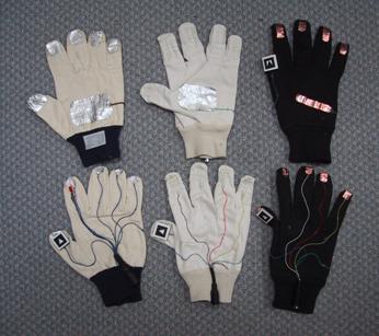
The glove
design is based on typical fabric gloves available in many supermarkets and
hardware stores, with wires and connectors glued to the surface. The gloves are
quite simple in operation and rely on the completion of an electric circuit -
conductive surfaces on the fingers, thumbs, and palms detect when various pinch
motions occur. Initially, a partially conductive aluminium tape was used as the
surface, but this did not conduct well and was difficult to attach to the
wires. Further improvements used metallic wire wrapped and glued around the
fingertips, giving improved conduction and pinch detection but being more
fragile. The latest design is based around 3M copper adhesive tape, which gives
the best conduction and is also extremely robust. The three glove designs with
aluminium tape, wire, and copper tape are shown in Figure 7‑11.
|
|
|
Figure 2‑11 Designs of various versions of the glove and attached fiducial markers Shown are aluminium tape, wire wound, and copper tape designs |
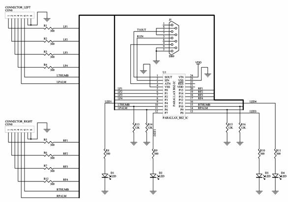
Wires from the metallic surfaces are attached to the glove controller box mounted inside the backpack via connectors on the shoulder straps. The controller box contains a Basic Stamp BS2 microcontroller [PARA01] that uses very little power and is fully functional in a small 24 pin IC sized package. The circuit depicted in Figure 7‑12 connects the BS2 to the gloves with a minimal number of components. The internal software applies voltage to each finger and polls for which pad the voltage is detected on (thumb, palm, or none). If this value is different from the last loop, a single byte packet is sent to the serial port on the laptop for processing, containing the current status of the changed finger. Since the microcontroller is dedicated to the task, there is no overhead for the laptop and the polling can operate in a hard real-time loop at 30 Hz. As the design of the gloves changes, the controller can be upgraded by downloading new firmware through the serial port.
1.3.2 Glove tracking
|
|
The gloves are used to capture the 3D position of the hands so the user can intuitively control the outdoor AR system. As described in the background chapter, tracking in an outdoor environment suffers from a number of known problems such as power consumption, size, weight, and support infrastructure. The outdoor environment also contains harsh conditions that cannot be controlled by the user. Some examples of these problems are:
· Accelerometers cannot be used since they drift over time and the registration of the cursor would be inadequate for accurate modelling tasks.
Infrared-based systems are unreliable when used outside due to the large amounts of infrared light given off by the sun.
Active magnetic tracking relies on using large non-portable control units, consumes large amounts of electric power, and would be affected by magnetic fields from the equipment carried on the backpack.
One solution demonstrated outdoors was the WearTrack system [FOXL00] by Foxlin and Harrington that utilised ultrasonic technology. This system tracked the position of the user’s hand relative to their head (with no orientation), and was used for a number of interaction tasks. To implement this system, an ultrasonic tracker with its associated weight, size, and electric power penalties must be added to the wearable computer system.
The
solution created for this dissertation uses optically-based vision tracking.
This approach allows me to leverage the existing helmet mounted camera that is
currently used for the live AR video overlay. The ARToolKit libraries [KATO99]
are employed to perform full six degree of freedom tracking of the fiducial
markers placed on the thumbs of the gloves. Currently only the position values
are used, as the accuracy of the rotation values is not adequate. Implementing
vision tracking with the gloves simply requires the attachment of small and
lightweight paper-based fiducial markers, with no extra devices or batteries
required. The paper markers used in this implementation are 2cm x 2cm squares
and are glued to the thumbs of the glove. Another advantage of my vision-based
tracking implementation is that achieving accurate registration is relatively
simple using the video from the AR overlay.
|
|
1.3.3 Fiducial marker placement
It was initially proposed to put the fiducial markers on the back of the user’s hands, but it was quickly realised that the hands are large and fill much of the field of view of the camera. A user would not be able keep the markers in the field of view and manipulate an object to the edge of the display. The problem of accurately calculating the user’s finger tip position based on fiducial markers on the wrists was also a concern. It was decided that the index fingertips would not obscure the user’s view, allow much finer motor control, and provide extended movement. The ends of the index fingers were dismissed during simple trials however, as they moved during menu option selections and would affect operations in progress. I did however notice that the thumb only moved slightly during the pinch motion, and the users studied tended to bring their fingers to meet their thumb as opposed to moving the thumb to meet the fingers. The targets were then placed at the tips of the thumb in an orientation that is fully visible to the camera when the gloves are used for interaction and menu operations, as shown in Figure 7‑13.
1.3.4 ARToolKit calibration
The ARToolKit libraries [KATO99] were developed to support the tracking of simple fiducial markers, allowing applications to appear to place 3D objects onto these markers when viewed on a display device – an example is the ARToolKit simpleTest demonstration. While the ARToolKit generates 6DOF matrices for each fiducial marker, these matrices are expressed using a special distorted camera frustum model and not usually in true orthogonal world coordinates. If the calibration model for the camera is an accurate model, it is possible to treat these camera coordinates directly as world coordinates. If the calibration model for the camera is not perfect (the ARToolKit calibration process does not always generate good results) then extra errors are introduced during the conversion and it is unusable for tracking. I have developed a method of correcting the calibration values so that the ARToolKit may be used for tracking and inserting results into a scene graph [PIEK02f].
In applications that use ARToolKit as intended (such as simpleTest), the video is first captured by libARvideo. Next, recognition of fiducial markers and calculation of camera-space transformations is performed in libAR, which is then used to render the final scene using the camera calibration frustum in libARgsub. When a pattern is recognised, a matrix transformation is returned from arGetTransMat(), which defines the marker’s position and orientation (6DOF) relative to the camera, in the camera’s calibrated coordinate system. The camera calibration data is used by this function to modify the results to compensate for the camera’s unique properties. Due to distortions in the camera and errors in the calibration process, the coordinate system is not the typical orthogonal coordinate system normally used in 3D graphics. If this camera-space matrix is used to draw an object with libARgsub, the view frustum used in OpenGL will be the same as that of the camera model, and so the image will appear to be rendered at the correct location. An interesting side effect of these transformations is that no matter how poor the camera calibration is, the 3D object overlaid on the fiducial marker will always be correct since the incorrect calibration model used in arGetTransMat() is reversed when drawing using the camera as the view frustum in libARgsub. When the matrix calculated in arGetTransMat() is put into a scene graph however, errors occur in the output for two reasons. The first is that the camera calibration is not being used to render the display and compensate for any camera distortions. Secondly, if the calibration is not good enough and did not model the camera accurately, further errors are introduced.
After
calibration of a camera, ARToolKit generates information for the camera similar
to that depicted on the left in Figure 7‑14. The values that define the
coordinate system of the camera (and also found to introduce the most errors)
were the X and Y values for the centre pixel of the camera and the other values
in the matrix (highlighted with boxes). In the default supplied calibration
file, the Y axis is 48 pixels from the centre of the camera but under testing I
found most cameras had centres that were reasonably in the middle. This was an
error introduced during the calibration process that requires correction before
use, and forms the basis of my calibration technique.
|
|
|
Figure 2‑14 ARToolKit default camera_para.dat file, with error x=2.5, y=48.0 The model is then corrected so the axes are orthogonal and usable as a tracker |
The
values generated by the ARToolKit calibration procedure (as depicted in Figure
7‑14) are stored in a binary file that can be easily modified. The
technique is to adjust the highlighted values but leave the focal point and
scale values untouched because they are reasonably correct and errors are less
noticeable. The highlighted values are replaced with the coordinates exactly at
the centre of the display, with 320x240 being used for a 640x480 resolution
camera. These changes are based on the assumption that most cameras are
straight and that any offsets in this value are caused by errors in the
calibration process and not in the camera itself. Figure 7‑15 depicts the
effects of these changes graphically, where the original distorted camera is
now orthogonal and suitable for use as a tracking device in a scene graph. This
technique is only useful for correcting errors caused by the ARToolKit
calibration with cameras that have the centre of the image at approximately the
axis of the camera. In distorted cameras, this technique could produce results
that are worse than the uncorrected version, and so should be used with care
and the results carefully monitored to ensure that it is being used in an
appropriate fashion.
|
|
1.3.5 Tracking results
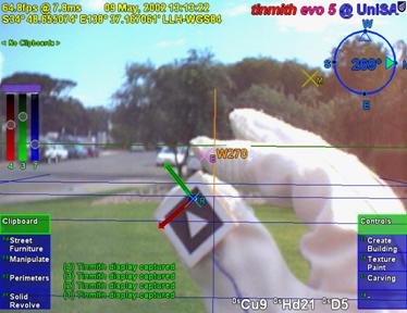
Although vision tracking may be CPU intensive, the ARToolKit runs quite efficiently on the laptop and works alongside the rest of the software with no noticeable problems. The 1394 camera mounted on the user’s head captures the video for the video overlay and also passes it to the ARToolKit subsystem for further processing. Dynamic lighting conditions may cause problems for the tracking since the camera automatically adjusts its settings for the overall image. Sometimes the resulting image may be too bright or lacking enough contrast to produce the thresholded binary image for the ARToolKit library to extract the fiducial markers, and so the tracking fails. I intend on experimenting further with different cameras and filters to help improve the ability to handle the bright and varying lighting conditions outdoors. In dark twilight conditions, the tracker works quite reliably due to the low light gathering capabilities of the camera, and a small light attached to the HMD may be used in cases of complete darkness.
Although there are some problems, the tracker is usually able to acquire the fiducial markers and provide tracking information to the rest of the system. When used for 3D positioning the results from the vision tracker is quite good and the registration is within the area of the target. However, detecting 3D rotation is more error prone since large changes in orientation only give small changes in perspective on the image, resulting in very noisy output in the order of 20-30 degrees. As a result, I currently only use ARToolKit for position tracking, providing a cursor for use on the HMD. Chapter 5 described how by combining two cursors it is possible to derive a high quality rotation using their relative positions.
Using ARToolKit as a general purpose tracker with some adjustments has allowed me to integrate hand tracking into my outdoor modelling applications that may otherwise have not been possible given the conditions in the outdoor environment. Since the user interface described in Chapter 5 has evolved to use only 2D position information, much simpler tracking may be performed using algorithms such as blob detection. Coloured balls with non-specular surfaces mounted onto the thumbs are much easier to detect even under poor lighting, and would improve interactive performance and tracking quality for the user.
1.4 Summary
This chapter has presented the hardware components used to perform mobile outdoor AR and to support the applications developed for this dissertation. The components used are mostly based on commercially available devices since specific equipment designed for mobile AR is not available. A new backpack named Tinmith-Endeavour was developed to provide a flexible platform for the carrying of the required components outside. This new design takes advantage of lessons learned over many years of backpack design and is expandable to handle changes in the future. To provide input for the user interface described in this dissertation, a new input device based on pinch detecting gloves and fiducial markers was developed. Both the backpack and gloves have been tested extensively and iteratively refined as part of this dissertation research.